- 您现在的位置:买卖IC网 > Sheet目录307 > ADM8843ACPZ-REEL7 (Analog Devices Inc)IC LED DRVR WHITE BCKLGT 16LFCSP
�� �
�
�ADM8843�
�AUTOMATIC� GAIN� CONTROL�
�The� automatic� gain� control� block� controls� the� operation� of� the�
�charge� pump� by� selecting� the� appropriate� gain� for� the� charge�
�pump.� Doing� so� maintains� sufficient� drive� for� the� LED� anodes�
�at� the� highest� power� efficiency� over� a� 2.6� V� to� 5.5� V� input�
�supply� range.� The� charge� pump� switching� thresholds� are�
�described� in� Table� 5.�
�Table� 5.� Charge� Pump� Switching� Thresholds�
�Gain� Threshold� (V)�
�1.5� to� 2� 3.33�
�2� to� 1.5� 3.36�
�1� to� 1.5� 4.77�
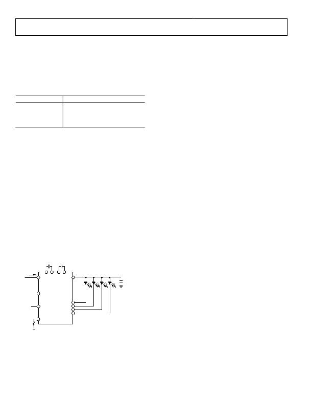
�Applying� a� digital� PWM� signal� to� one� or� both� digital� input�
�control� pins,� CTRL1� and� CTRL2,� adjusts� the� brightness� of� the�
�sub� and/or� main� displays.� The� ADM8843’s� four� white� LEDs� are�
�organized� into� two� groups,� main� display� (FB1� to� FB3)� and� sub�
�display� (FB4);� refer� to� the� Theory� of� Operation� section.�
�The� brightness� of� the� ADM8843’s� main� and� sub� displays� can� be�
�controlled� together� or� separately.� This� is� achieved� by� applying� a�
�digital� PWM� signal� to� both� the� CTRL1� and� CTRL2� pins.� The� duty�
�cycle� of� the� applied� digital� PWM� signal� determines� the� brightness�
�of� the� main� and� sub� displays� together.� Varying� the� duty� cycle� of�
�the� applied� PWM� signal� varies� the� brightness� of� the� main� and�
�sub� displays� from� 0%� to� 100%.�
�1.5� to� 1�
�4.81�
�By� holding� CTRL1� low� and� applying� a� digital� PWM� signal� to�
�CTRL2,� the� sub� display� is� turned� off� and� the� main� display� is�
�BRIGHTNESS� CONTROL� WITH� A�
�DIGITAL� PWM� SIGNAL�
�PWM� brightness� control� provides� the� widest� brightness� control�
�method� by� pulsing� the� white� LEDs� on� and� off� using� one� or� both�
�digital� input� control� pins,� CTRL1� and� CTRL2.� PWM� brightness�
�control� also� removes� any� chromaticity� shifts� associated� with�
�changing� the� white� LED� current,� because� the� LEDs� operate� at�
�either� zero� current� or� full� current� (set� by� R� SET� ).�
�The� digital� PWM� signal� applied� with� a� frequency� of� 100� Hz� to�
�200� kHz� turns� the� current� control� sinks� on� and� off� using� CTRL1�
�and/or� CTRL2.� The� average� current� through� the� LEDs� changes�
�with� the� PWM� signal� duty� cycle.� If� the� PWM� frequency� is� much�
�less� than� 100� Hz,� flicker� may� be� seen� in� the� LEDs.� For� the�
�ADM8843,� zero� duty� cycle� turns� off� the� LEDs,� and� a� 50%� duty�
�cycle� results� in� an� average� LED� current,� I� LED� ,� that� is� half� the� pro-�
�grammed� LED� current.� For� example,� if� R� SET� is� set� to� program�
�20� mA/LED,� a� 50%� duty� cycle� results� in� an� average� I� LED� of�
�10� mA/LED,� which� is� half� the� programmed� LED� current.�
�turned� on.� Then� the� brightness� of� the� main� display� is� determined�
�by� the� duty� cycle� of� the� applied� digital� PWM� signal.�
�By� applying� a� digital� PWM� signal� to� CTRL1� and� holding� CTRL2�
�low,� the� sub� display� is� turned� on� and� the� main� display� is� turned�
�off.� Then� the� brightness� of� the� sub� display� is� determined� by� the�
�duty� cycle� of� the� applied� digital� PWM� signal.�
�By� applying� a� digital� PWM� signal� to� CTRL1� and� holding�
�CTRL2� high,� the� sub� display� is� turned� on� and� the� main� display�
�is� turned� on.� Then� the� brightness� of� the� sub� display� is� determined�
�by� the� duty� cycle� of� the� applied� digital� PWM� signal.� The� bright-�
�ness� of� the� main� display� is� set� to� the� maximum� (maximum� is� set�
�by� R� SET� ).�
�By� holding� CTRL1� high� and� applying� a� digital� PWM� signal� to�
�CTRL2,� the� sub� and� main� displays� are� turned� on.� Then� the�
�brightness� of� the� main� display� is� determined� by� the� duty� cycle� of�
�the� applied� digital� PWM� signal.� The� brightness� of� the� sub�
�display� is� set� to� the� maximum� (maximum� is� set� by� R� SET� ).�
�C1�
�1� μ� F�
�C2�
�1� μ� F�
�When� CTRL1� and� CTRL2� are� low,� the� LED� current� control�
�sinks� shutdown.� Shutdown� of� the� charge� pump� is� delayed� by�
�3.4V� I�
�IN�
�V� CC�
�ADM8845�
�V� OUT�
�C3�
�2.2� μ� F�
�15� ms.� This� timeout� period,� t� CP� ,� allows� the� ADM8843� to�
�determine� if� a� digital� PWM� signal� is� present� on� CTRL1� and�
�CTRL2,� or� if� the� user� has� selected� a� full� chip� shutdown� (see�
�PWM� INPUT�
�OR�
�HIGH/LOW�
�CTRL1�
�Figure� 20).�
�PWM� INPUT�
�OR�
�HIGH/LOW�
�CTRL2�
�FB1�
�FB2�
�FB3�
�FB4�
�If� digital� PWM� brightness� control� of� the� LEDs� is� not� required,� a�
�constant� Logic� Level� 1� (V� CC� )� or� Logic� Level� 0� (GND)� must� be�
�applied.�
�I� SET�
�R� SET�
�Figure� 19.� Digital� PWM� Brightness� Control� Application� Diagram�
�The� four� white� LED� in� the� ADM8843� are� arranged� into� two�
�groups,� sub� and� main.� It� is� possible� to� configure� the� four� LEDs�
�as� in� Table� 6.� Refer� also� to� Figure� 20.�
�Rev.� C� |� Page� 10� of� 16�
�发布紧急采购,3分钟左右您将得到回复。
相关PDF资料
ADP1653ACPZ-R7
IC LED DRVR PHOTO FLASH 16-LFCSP
ADP1712-EVALZ
BOARD EVALUATION ADP1712
ADP1720-EVALZ
BOARD EVAL FOR ADP1720-ADJ
ADP2140CPZ-REDYKIT
REDYKIT 2 BOARDS ADP2140ACPZ
ADP3110AKRZ-RL
IC MOSFET DRIVER DUAL 12V 8SOIC
ADP3120AJCPZ-RL
IC MOSFET DRIVER DUAL 12V 8-DFN
ADP3121JRZ-RL
IC MOSFET DRIVER DUAL 12V 8SOIC
ADP3415LRMZ-REEL
IC MOSFET DVR DUAL BOOTST 10MSOP
相关代理商/技术参数
ADM8843ACUZ-REEL7
制造商:Analog Devices 功能描述:
ADM8843EB-EVALZ
功能描述:BOARD EVAL ADM8843 RoHS:是 类别:编程器,开发系统 >> 评估板 - LED 驱动器 系列:- 标准包装:1 系列:PowerWise® 电流 - 输出 / 通道:20mA 输出及类型:1,非隔离 输出电压:17V 特点:可调光 输入电压:2.7 ~ 5.5 V 已供物品:板 已用 IC / 零件:LM3508 相关产品:LM3508TLX-ND - IC LED DRVR WHT BCKLGT 9USMDLM3508TLDKR-ND - IC LED DRVR WHT BCKLGT 9MICROSMDLM3508TLCT-ND - IC LED DRVR WHT BCKLGT 9MICROSMDLM3508TLTR-ND - IC LED DRVR WHT BCKLGT 9MICROSMD
ADM8845
制造商:AD 制造商全称:Analog Devices 功能描述:Charge Pump Driver for LCD White LED Backlights
ADM8845ACP
制造商:Analog Devices 功能描述:CHG PUMP STPUP 30MA 16LFCSP - Bulk
ADM8845ACP-REEL
制造商:Analog Devices 功能描述:Charge Pump STPUP 30mA 16-Pin LFCSP EP T/R
ADM8845ACP-REEL7
制造商:Analog Devices 功能描述:Charge Pump STPUP 30mA 16-Pin LFCSP EP T/R
ADM8845ACPZ
制造商:AD 制造商全称:Analog Devices 功能描述:Charge Pump Driver for LCD White LED Backlights
ADM8845ACPZ-REEL
功能描述:IC LED DRVR WHITE BCKLGT 16LFCSP RoHS:是 类别:集成电路 (IC) >> PMIC - LED 驱动器 系列:- 标准包装:6,000 系列:- 恒定电流:- 恒定电压:- 拓扑:开路漏极,PWM 输出数:4 内部驱动器:是 类型 - 主要:LED 闪烁器 类型 - 次要:- 频率:400kHz 电源电压:2.3 V ~ 5.5 V 输出电压:- 安装类型:表面贴装 封装/外壳:8-VFDFN 裸露焊盘 供应商设备封装:8-HVSON 包装:带卷 (TR) 工作温度:-40°C ~ 85°C 其它名称:935286881118PCA9553TK/02-TPCA9553TK/02-T-ND